- 1. Active Alignment: The Core Reason for Dual-Cure in Camera Bonding
- 2. Why ADAS Camera Modules Are Particularly Affected by Shadow Areas
- 3. How Shadow Areas Form in ADAS Camera Assembly
- 3. Dual-Cure UV Adhesives: The Technical Approach to Shadow Area Management
- 5. How Adhesive Application Affects Shadow Area Severity
- 6. Prostech: Technical Support for Camera Adhesive Applications
In high-precision electronics manufacturing, achieving perfect optical clarity while maintaining high throughput is a constant struggle. This precision is often threatened by shadow areas – zones where UV light cannot reach. This article explains in detail why electronics products assembly, specifically camera module assembly needs dual-cure adhesives.
1. Active Alignment: The Core Reason for Dual-Cure in Camera Bonding
In ADAS camera assembly, optical precision is non-negotiable. A misalignment of even 30 microns at the image sensor position can lead to significant degradation in image quality, potentially compromising vehicle safety.

Source: Prostech
1.1. The 6-DOF Precision Requirement
Unlike passive alignment, which relies on mechanical tolerances of parts, Active Alignment is a real-time adjustment process. It allows for adjustments across 6 degrees of freedom (X, Y, Z, and 3 rotational axes) while the sensor is powered on.
1.2. The Dual-Stage Curing Logic
The typical process flow is: Dispense → Assemble → Active Align (real-time) → UV Fix → Thermal Post-cure.
UV Fix Step: Acts as a “flash-freeze,” locking the optical components in their optimized positions within seconds. This ensures alignment is maintained as the module moves to the next station.
Thermal Post-cure: Completes the chemical reaction in shadow areas where UV light cannot penetrate, ensuring the joint reaches its full structural integrity.
2. Why ADAS Camera Modules Are Particularly Affected by Shadow Areas
2.1. The Assembly Architecture Behind the Problem
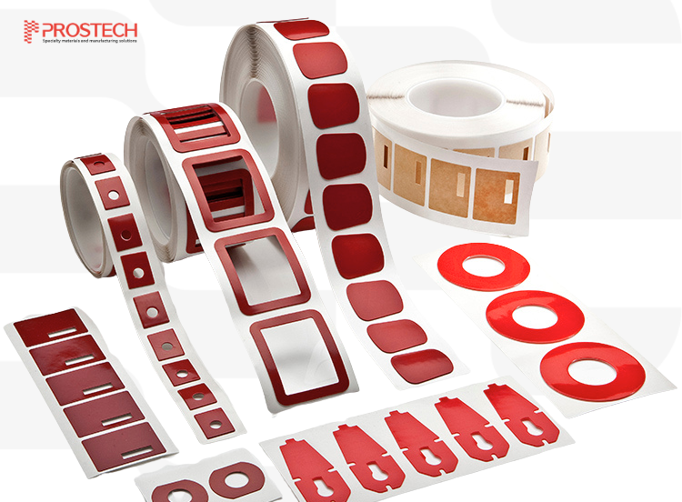
An ADAS camera module integrates multiple optical, mechanical, and electronic sub-components, such as lens elements, lens barrels, IR cut filters, CMOS image sensors, voice coil motors (VCMs), and flexible printed circuits (FPCs), within a compact housing. Each sub-component must be bonded at a precisely controlled position to maintain the optical alignment the camera needs to deliver usable image data to the vehicle’s central processing unit.
Refer to this article for essential information about specialty materials for camera modules.
This structural density creates recessed joints, overlapping flanges, and enclosed cavities throughout the module. In many of these locations, the adhesive bond line is not accessible to UV light from the curing station. These inaccessible zones are the shadow areas specific to camera module assembly – and they are a direct consequence of the module’s geometry, not a process design error.
Need technical consultations on your own assembly line?
2.2. Regulatory Context: Mandatory ADAS in New Vehicles
The demand for reliable ADAS camera assembly has grown alongside the regulatory environment under the General Safety Regulation (GSR2 – Regulation EU 2019/2144) and Regulation 171 on Driver Control Assistance Systems (DCAS) (US).
As regulatory compliance drives ADAS camera adoption across both conventional internal combustion engine vehicles and electric vehicles (EVs), shadow area management in ADAS camera assembly is no longer a process refinement – it is a qualification prerequisite.
3. How Shadow Areas Form in ADAS Camera Assembly
3.1. Two Distinct Sources
Shadow areas in ADAS camera assembly arise from two separate mechanisms, which can occur independently or simultaneously at the same bond joint:
Geometry-induced shadow areas form when surrounding components physically block UV light from reaching the bond line. The adhesive is present and dispensed correctly, but photons from the curing station cannot travel to it along a direct path.

Source: Prostech
Depth-induced shadow areas form when the dispensed adhesive bead height exceeds the UV cure depth of the formulation being used. Even in a zone with direct UV exposure, the lower portion of a thick bead does not receive sufficient photon flux to complete polymerization. This is a material and process parameter limitation, not a geometry problem, and it occurs regardless of UV lamp power or exposure duration.

Source: Prostech
While geometry-induced shadows are addressed through chemistry (Dual-cure mechanisms), depth-induced shadows are a process-control challenge that must be addressed through precision dispensing parameters.
Receive free technical assessment of your problems here.
3.2. Bond Interfaces Where Shadow Areas Occur in ADAS Camera Modules
The following bond points are consistently identified as shadow area locations in automotive camera module production:
Bond Point | Primary Reason for Dual Cure | Are Shadow Areas a Real Concern? |
Barrel-to-holder (AA) | Process control — locking position | Yes, but secondary to alignment fix |
Holder-to-PCB | Structural fixation | High — due to recessed geometry |
VCM fixation | Structural integrity (no alignment needed) | High — shielded by motor flanges |
FPC reinforcement | Protective, non-structural | High — shielded by connector shroud |
IR filter bonding | Non-structural, protective | High — recessed in cavity |
Struggling with choosing proper adhesives for your bond points? Let our expert assist.
2.3. The Physics of UV Cure Failure in Shadow Zones
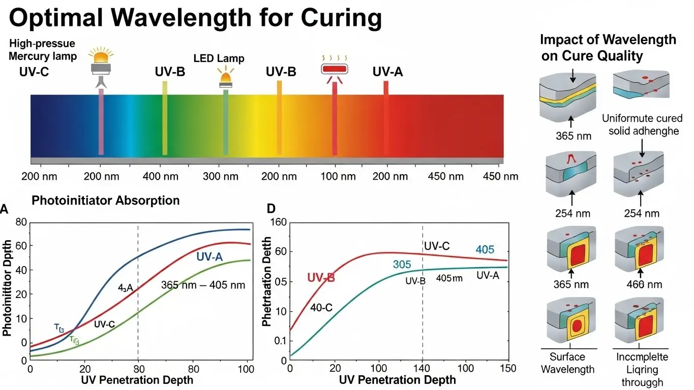
Photopolymerization requires photons at specific wavelengths – typically 365 nm to 405 nm for the photoinitiators used in most industrial UV adhesive formulations – to excite photoinitiator molecules. The excited photoinitiators generate free radicals or cationic species that initiate chain polymerization throughout the resin.
Source: UVET
This reaction has one fundamental constraint: photons travel in straight lines. Although diffraction around edges is a physical phenomenon, the wavelengths used in industrial UV curing (365–405 nm) are far too short relative to the millimeter-scale shadow geometries of camera modules for diffracted light to deliver curing -grade energy.
Any bond line outside the direct line-of-sight from the UV source receives effectively zero curing energy, regardless of lamp intensity or exposure time.
2.4. Substrate Material as an Additional Source of UV Blockage
ADAS camera module housings and lens holders are predominantly manufactured from LCP (Liquid Crystal Polymer) and PPS (Polyphenylene Sulfide). These engineering thermoplastics are typically compounded with carbon black or dark pigments to suppress internal optical reflections that reduce image contrast and introduce stray light artefacts.

Source: Prostech
As a result, these materials are opaque to UV wavelengths in the 365–405 nm range. Even where the geometry of a bond line appears accessible, the substrate material itself blocks UV transmission. The adhesive beneath an opaque flange or inside a recessed pocket cannot initiate polymerization regardless of UV lamp positioning.
Need material advice on your own part? Contact our technical team now.
3. Dual-Cure UV Adhesives: The Technical Approach to Shadow Area Management
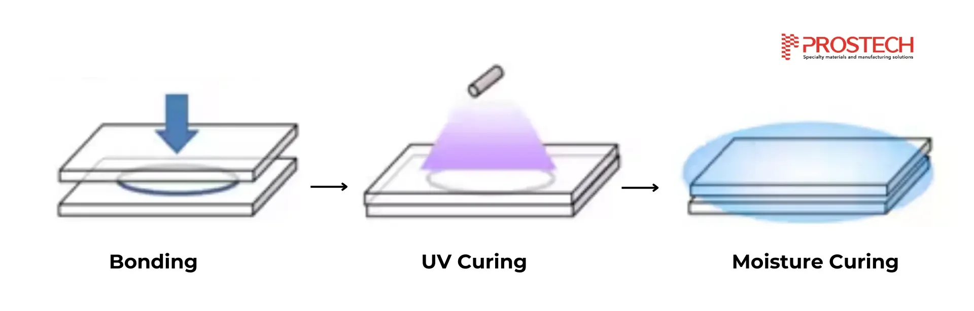
The standard approach to managing shadow areas is the use of dual-cure UV adhesives – formulations that combine a primary UV cure mechanism with a secondary, light – independent curing pathway.
Zones with direct UV access cure immediately when the lamp activates, fixing components in their aligned positions. Zones in shadow complete polymerization through the secondary mechanism, without requiring repositioning, additional UV fixtures, or manual intervention.
Take a look at three secondary cure mechanisms are used in ADAS camera module production:
4.1. UV + Thermal (Heat) Cure – Standard for Active Alignment
UV + thermal dual cure is the predominant approach for the active alignment step in automotive camera module assembly. This is the critical bond joint that determines whether the camera maintains its optical specification throughout vehicle service life.
The assembly sequence is as follows: dispense → place → align → UV fix → thermal post-cure.

Source: Prostech
Key highlights of this application are:
- Speed: Thermal post-cure at 80–85°C completes in 15–30 minutes, fitting modern production time. In contrast, moisture cure can take hours or days.
- Predictability: Heat provides consistent, uniform curing throughout the module, essential for maintaining the sub-micron stability of the AA joint.
- Protection: Low-temperature thermal cure (80–85°C) protects sensitive optical coatings that might degrade at 130°C+ .
Product Recommendation: Gluditec UV5103H
Not sure if your application should apply UV + thermal dual cure? Let our experts validate.
4.2. UV + Moisture Cure – For Non-Structural Applications
For PCB conformal coating, FPC encapsulation, and connector sealing within camera module assemblies – where the bond function is protective rather than structural – UV + moisture dual-cure formulations are used. The UV primary cure provides immediate surface handling strength. The secondary moisture-cure mechanism then propagates through shadow zones using ambient humidity.
Source: Prostech
The cure timeline of the secondary mechanism is measured in hours, which is a production planning consideration in high -volume manufacturing. This mechanism is not suited for active alignment bond joints where full mechanical performance is required before the module moves to subsequent assembly or test stages.
Product Recommendation: AU009-1; Gluditec UV3109-M; Chemtronics UR-101
Not sure if your application should apply UV + moisture dual cure? Let our experts validate.
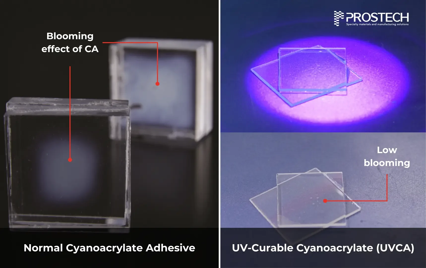
4.3. UV – Curable Cyanoacrylate (UVCA) – For Opaque Substrate Bonding
UV – Curable Cyanoacrylate (UVCA) combines UV cure with the anionic moisture – activated secondary cure inherent to cyanoacrylate chemistry. In ADAS camera assembly, UVCA is considered for joints where bonding opaque, UV – blocking plastic components is required and where applying a thermal cure stage would risk damaging thermally sensitive optical coatings or sub-assemblies.
A relevant property of UVCA in optical assembly is reduced blooming – the white, powdery surface residue associated with standard cyanoacrylate cure outgassing – which can contaminate lens surfaces and filter glass if it occurs near the optical path.
Refer to this article to thoroughly understand the blooming effect.
Source: Prostech
Note:
For low surface energy substrates such as LCP and PPS, surface activation through plasma treatment or a compatible primer is required prior to bonding.
For bond lines in the direct optical path (lens-to-sensor), Epoxy adhesives remain the industry standard due to their superior dimensional stability and lower outgassing profile
5. How Adhesive Application Affects Shadow Area Severity
Dual-cure formulations address the chemical limitation of shadow areas. However, the physical parameters of adhesive application determine whether the dual-cure mechanism can function as designed.
5.1. Bead Geometry and UV Cure Depth
For clear optical adhesives used in lens bonding, UV cure depth may reach several millimeters under adequate lamp intensity.
For pigmented or carbon-filled structural adhesives – which are common in automotive camera module assemblies using black-housing components – effective UV cure depth may be as low as 0.5–1.0 mm.
When the dispensed bead height exceeds the formulation’s rated cure depth, the lower portion of the bead remains uncured even in a geometrically accessible zone.
Controlling dispensed bead volume and height is therefore a direct shadow area management measure, not only a process cleanliness consideration.
5.2. Automated Dispensing for Consistent Volume Control
Manual adhesive application does not provide the volume control, placement accuracy, or process repeatability needed to consistently manage shadow areas in ADAS camera production. Automated dispensing equipment is the production standard for this application. Specifically, the following capabilities are required from an automated dispensing platform:
Volume control: Jetting or auger-valve dispensing systems deliver adhesive volumes with positional accuracy better than ±50 μm and volume repeatability of ±1–2%..

Source: Prostech
3D bead profiling: Robotic dispensing platforms execute programmed adhesive bead profiles around complex 3D joint geometries – lens barrel attach, VCM perimeter, lens housing, PCB joint, with positional accuracy better than ±50 μm.
Vision-guided correction: Inline machine vision locates component reference features and adjusts dispensing coordinates to compensate for component-to-component placement variation.
Synchronized UV curing: Dispensing and UV curing are integrated so that UV pre-cure is applied while the aligned components are held in position, before any positional relaxation occurs.
These capabilities directly reduce adhesive volume variation as a source of depth-induced shadow areas, and maintain the process consistency required for automotive qualification.
Take a look at high quality dispensing systems here.
6. Prostech: Technical Support for Camera Adhesive Applications

Source: Prostech
Prostech distributes and provides application support for a wide range of dual-cure UV adhesive products used in ADAS camera modules and automotive electronics assembly.
For technical data sheets, material samples, or application consultation, contact Prostech’s technical team directly.