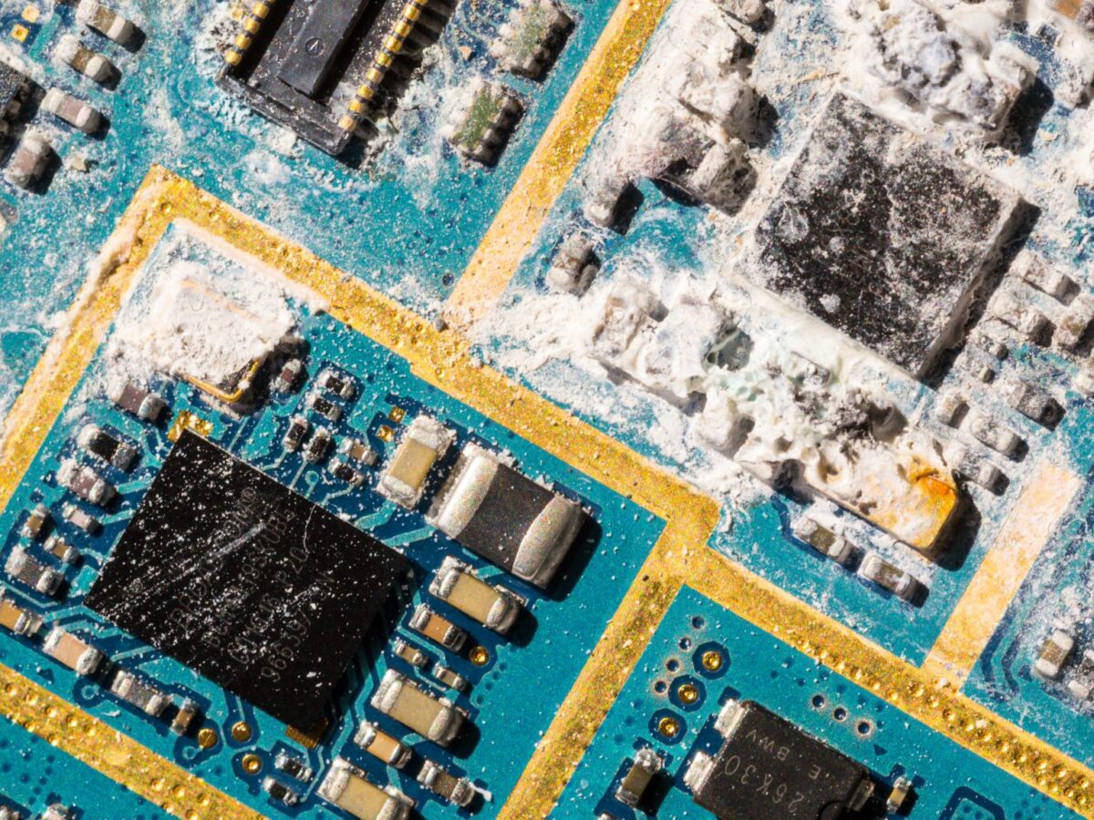
The appearance of white residue on PCB (printed circuit board) is often found after the cleaning step. Most residues are the result of insufficient or incomplete cleaning and can be removed by simply repeating the cleaning step. Unfortunately, there is another type of PCB residues that results from more complex chemical reactions between soldering flux, cleaning solvents, the soldering process, the board laminate, and process parameters such as line speed and soldering temperature. These is the dreaded white residue that is frequently difficult to remove with standard circuit board cleaners.
How many types of white residue are there?
Circuit board white residues are classified into two types:
Ionic residue
If ionic residues are left on the board, they can cause corrosion. Ionic residues can form due to the nature of the soldering flux, the soldering process and cleaning parameters, or incompatibility with cleaning solvents. If not properly cleaned, R, RA, and aqueous fluxes will all leave ionic residues. When exposed to soldering temperature and activated, no-clean fluxes consume the ionic material. However, any inactivated no-clean flux, like any other, can leave behind ionic residues.
Organic residue
Organic residues are less serious, but they detract from the appearance of the board and can cause conformal coating adhesion issues. Organic residues are formed as a result of poor soldering or cleaning techniques, or as a mismatch between the flux and the appropriate flux remover.
The type of contamination on the board is simple to identify. With a drop of water, test each patch of residue. It is ionic if the water dissolves the residue. If not, use a drop of isopropyl alcohol to test (IPA). It’s organic if it dissolves the residue. This tells you quickly what you’ll need to clean the board (either a water-based cleaner or a solvent-based cleaner) and can give you an idea of what’s causing the problem. In both cases, the contamination problem is more likely to be the result of poor technique or incomplete cleaning.
What causes white residue on PCB?
Ionic contamination is frequently caused by the type of soldering flux used. Many water-soluble fluxes, as well as rosin and rosin-based no-clean fluxes, contain varying amounts of halide acid activators. These activators improve flux heat stability and aid in the formation of good solder joints by dissolving the oxide films that contaminate copper, lead, and tin surfaces.
The chemical reaction of these activators’ chloride and bromide ions with the lead in tin-lead solder can result in the formation of white lead chloride and lead carbonate residue around the solder joints. If these ions are not completely removed during cleaning, they can start a continuous corrosion cycle, producing more lead chloride, lead carbonate (white residue), and hydrochloric acid, which will attack the copper in the board laminate.
To make matters worse, when current is applied, ionic particles can form conductive branches known as dendrites. Dendrites form between contact points and either causes current leakage or an electrical short.
Organic rosin residues can form in a variety of ways.
– Oxidation: The double bonds of the resin acids are involved in rosin oxidation during heating. The oxidized rosin is much less soluble in solvents than the original rosin and, after cleaning a circuit board assembly, remains irregularly distributed as a white film on the surface. The rosin is oxidized due to the excessive amount of heat required (heat is the temperature for a time).
– The acid carboxyl group: During soldering, the acid carboxyl group also reacts. Because tin can be found in the white residue, a portion (less than 10%) of the residue could be a reaction product of tin oxide and the resin acids. Because the resultant compound is formed with pimaric acids, it is often referred to as tin abietate rather than tin resinate.
– Activators: Activators which consist of halides (chlorides or bormides) and halogens capable of liberating halides also can result in white residues.
– Solvent: A chlorinated or fluorinated solvent can be a source of chloride residue. Inhibitors are added to help prevent degradation, but when chlorides from flux and water from condensation are present, the solvent can “go acid” and cause chloride formation.
– Solder mask: Solder mask is another major cause of white residues. Incompletely cured solder mask can be caused by a formulation error, a lack of heat for infrared cured types or a lack of heat for ultraviolet cured types.
In case you haven’t heard, WIDEN YOUR KNOWLEDGE with the basic guideline of Soldering with our E-BOOK: Basic Guideline of Soldering for Beginners – Pros Technology
– Laminate: Laminate may also be partially cured if the board manufacturer made a mistake, or the resin was mis formulated. Without fully curing the epoxy, the carboxylic acid in the rosin can react with both the epoxy group and a hydroxyl group to form esters. Another explanation for white residue.
How to Solve the White Residue Issue
The following concerns can be addressed in order to eliminate the dreaded white residues from your PCB assemblies:
– Interval between soldering and cleaning: The longer flux residues remain on the circuit board, the more difficult it is to remove them. It is advised to clean them as soon as possible.
– Amount of flux used: Excessive flux or a high solids content increases the amount of material to be removed. Because of the variability of manual soldering, this is a particular problem. Even if no other changes are made to the cleaning process, best-practice training will often result in cleaner PCBs at the end of the line.
– Flux selection – R and RA fluxes are much easier to clean than no-clean fluxes, particularly the most recent halide-free varieties. That’s why R and RA fluxes are preferable options if the application needs cleaning later (of course there are more to consider in choosing a suitable flux). Aqueous fluxes are ideal for in-line or batch-cleaning equipment, but they are difficult to clean manually. Many solvent cleaners are ineffective on aqueous fluxes, and because these fluxes are highly active, they must be removed.
– Solvency match: The better the match between soil and cleaning solution, the less effort required and the fewer problems to solve. As a quick test, put a drop of cleaning solution on a PCB that has been flux-coated and run it through the reflow oven. Wipe it off after 1 or 2 minutes to see if it removed the flux from that area. If it does, it will be necessary to devise an effective cleaning procedure. If it doesn’t, find a more effective cleaner, or you’ll be fighting it all the time. Examining how the contamination coats the board reveals a general mismatch between the cleaner to the contamination type. Incomplete cleaning is indicated if the residue areas are patchy and increasing the cleaning time and/or temperature should help. If the contamination appears as an even layer across the board surface, you are not using the proper cleaner for the residue present.
– Cleaner residence time: With a good solvency match, it is simply a matter of determining the appropriate amount of exposure time required to fully clean the PCB. This would be accomplished in an inline cleaning system by adjusting the belt speed.
– Heating the cleaner: In general, the temperature of the cleaning solution increases solvency. Of course, for flammable cleaners, this is not an option for safety reasons. Temperature control is available on some cleaning equipment, such as ultrasonic, batch, and inline cleaning systems.
– Agitation in the cleaning process: If the solvency, exposure time, and temperature are optimized but there are still residues, you may need to add agitation. A brush, wipe, swab, powerful aerosol spray, ultrasonics, or jets in a cleaning system can all cause agitation. The position and pressure setting of the spray nozzle in an in-line cleaning system can also make a significant difference in cleaning effectiveness.