- What is EMI Shielding?
- Why EMI shielding is increasingly critical
- How Does EMI Shielding Work? The 3 Core Mechanisms
- Shielding Effectiveness Reference: What SE Values Mean in Practice
- Types of EMI Shielding Materials: Technical Comparison
- Deep-Dive: Key EMI Shielding Material Categories
- EMI Shielding Material Selection Guide
- EMI Shielding Standards and Compliance
- EMI Shielding Applications by Industry
- Electronic Devices and Components That Require EMI Shielding
- Frequently Asked Questions
- EMI Shielding Solutions from PROSTECH
EMI shielding (Electromagnetic Interference Shielding) is the practice of surrounding electronic components, circuits, or cables with conductive or magnetic barrier materials to block, reflect, or absorb electromagnetic interference (EMI), preventing signal degradation and ensuring regulatory compliance. As electronics become smaller, faster, and more densely packed — from 5G modules and automotive ECUs to medical implants and aerospace systems — selecting the right EMI shielding material is one of the most consequential engineering decisions in product design.
This guide gives engineers and procurement professionals the technical data they need: shielding effectiveness (SE) values in dB, frequency ranges per material type, conductivity data, selection criteria by application, and a direct comparison of the major EMI shielding material categories available today.
→ View Prostech EMI Shielding Product Portfolio
What is EMI Shielding?
EMI shielding is the use of a conductive or magnetic barrier to reduce the electromagnetic field within a protected space. In electrical engineering terms, the shield interrupts the path of electromagnetic energy — either by reflecting it at the surface, absorbing it within the material, or redirecting it through a controlled ground path.
As technology advances, many electronic devices need to be protected from electromagnetic interference to ensure stable and efficient operation. Devices such as heart monitors, mobile phones, industrial control systems, and aerospace equipment, etc. are all at risk of electromagnetic interference, which can cause disruptions and reduced performance. To ensure stable and accurate operation, electromagnetic interference (EMI) protection for these devices is essential. Here are some typical devices and components that require EMI protection measures:
- System-in-package (SIP)
- System-on-Chip (SoC)
- Microcontrollers (MCU)
- Application processors
- Power amplifiers
- Wireless modules (Wifi, Bluetooth)
- Radio Frequency (RF) modules
- Memory
- Sensors
- Digital signal processors (DSP)
- Application-specific intergrated circuits (ASIC)
- Field-programmable gate arrays (FPGA)
- Analog-Digital Converter (ADC).
Without adequate EMI shielding, electronic devices face two categories of risk:
- Susceptibility: External EM fields corrupt internal signals — causing data errors, false triggering of sensors, communication failures, or complete malfunction.
- Emission: The device itself radiates EM energy that interferes with nearby equipment — a compliance failure under FCC, CE, CISPR, and MIL-STD regulations.
Every electronic product that goes to market must demonstrate EMC (Electromagnetic Compatibility) — meaning it neither emits harmful levels of interference nor is adversely affected by its electromagnetic environment. EMI shielding is the primary engineering tool for achieving both goals.
Why EMI shielding is increasingly critical
Three converging trends are raising EMI stakes significantly:
- Higher clock frequencies and edge rates — modern processors and FPGAs operating above 1 GHz generate harmonics well into the microwave range.
- Increased wireless density — 5G (sub-6 GHz and mmWave), Wi-Fi 6/6E (6 GHz), UWB, and Bluetooth 5.x coexist in shrinking device footprints.
- Safety-critical applications — in automotive (ADAS, BMS), medical (implantable devices, diagnostic imaging), and aerospace, EMI failures can have life-safety consequences.
How Does EMI Shielding Work? The 3 Core Mechanisms
EMI shielding effectiveness is the result of three physical mechanisms that act simultaneously. Understanding each mechanism is essential for matching material selection to application requirements.
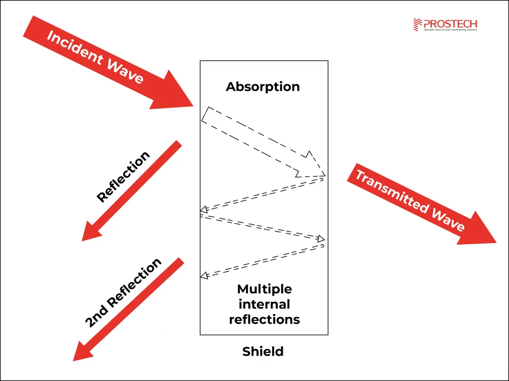
1. Reflection Loss (R)
Reflection is the dominant mechanism for solid metallic shields and is the primary reason copper and aluminum are widely used. When an EM wave encounters a conductive surface, the impedance mismatch between free space (377 Ω) and the low-impedance shield material causes most of the energy to be reflected back toward the source. Reflection loss increases with material conductivity and is largely independent of material thickness.
Key implication for design: Reflection is highly effective at high frequencies (>30 MHz) but provides little attenuation of low-frequency magnetic fields, where impedance mismatch is low.
2. Absorption Loss (A)
Energy that enters the shield is attenuated as it propagates through the material. The wave amplitude decays exponentially with depth — this decay length is known as the skin depth (δ):
δ = √(2 / ωμσ)
where ω is angular frequency, μ is magnetic permeability, and σ is electrical conductivity. At 1 GHz in copper, δ ≈ 2 μm — meaning even a 0.05 mm copper foil provides multiple skin depths of absorption. At 1 kHz in copper, δ ≈ 66 μm, meaning thick walls are required for low-frequency shielding.
Key implication for design: Absorption loss increases with frequency, material thickness, conductivity, and permeability. For low-frequency magnetic shielding (power transformers, MRI), high-permeability materials (mu-metal, silicon steel) are essential because they increase absorption loss per unit thickness.
3. Multiple Reflection (MR)
In thin shields and composite multi-layer materials, EM waves bounce between the inner and outer shield surfaces, providing additional attenuation. This mechanism is most significant when the material is thinner than the skin depth. In practical thick-metal shields at high frequencies, MR contributes negligibly — it is primarily relevant for thin foils, EMI absorber sheets, and multi-layer laminates like the 3M AB6000 series.
Total Shielding Effectiveness
The total SE of a material is the sum of all three contributions:
SE (dB) = R + A + MR
A shield with SE = 40 dB blocks 99.99% of the incident EM field. A shield with SE = 80 dB blocks 99.999999% — a critical distinction in medical and military systems where even trace interference can cause failures.
Shielding Effectiveness Reference: What SE Values Mean in Practice
| SE (dB) | EM Field Attenuation | Typical Requirement |
|---|---|---|
| 10–30 dB | 90–99.9% | Low-cost consumer electronics, minimal shielding |
| 40–60 dB | 99.99–99.9999% | Commercial electronics, IoT, industrial controls (FCC/CE compliance) |
| 60–80 dB | 99.9999–99.999999% | Automotive (CISPR 25), 5G infrastructure, high-performance industrial |
| 80–100 dB | >99.999999% | Medical devices (IEC 60601-1-2), aerospace, defense electronics |
| >100 dB | Essentially complete | Military enclosures (MIL-STD-285), secure communications (TEMPEST) |
Types of EMI Shielding Materials: Technical Comparison
EMI shielding materials fall into six primary categories. Each operates on different physical principles, covers different frequency bands, and suits different assembly methods. The table below provides a direct technical comparison — all SE values are typical ranges reported under standard test conditions (ASTM D4935 / IEEE Std 299).
EMI Shielding Materials Comparison Table
| Material Type | Electrical Conductivity (σ) | Effective Frequency Range | Typical SE (dB) | Primary Mechanism | Best For |
|---|---|---|---|---|---|
| Copper (solid / foil) | 5.8 × 10⁷ S/m | 10 kHz – 10 GHz+ | >100 dB | Reflection + Absorption | PCB cans, chassis enclosures, cable braids |
| Aluminum (alloy) | 3.5 × 10⁷ S/m | 30 MHz – 10 GHz | 60–100 dB | Reflection (primary) | Aerospace housings, EV battery enclosures, telecom |
| Stainless Steel | 1.1 × 10⁶ S/m | 100 kHz – 1 GHz | 40–80 dB | Reflection + Absorption | Industrial cabinets, medical enclosures |
| Mu-Metal / Silicon Steel | 1.6 × 10⁶ S/m (μr >20,000) | DC – 100 kHz | 80–130 dB (low-freq magnetic) | Absorption (high μ) | MRI rooms, sensor shielding, transformer cores |
| Conductive Silicone Elastomers (e.g., Ag-glass, Ni-graphite filled) | 10² – 10⁴ S/m (filled) | 10 MHz – 10 GHz | 70–110 dB | Reflection + Absorption | EMI gaskets, form-in-place seals, IP67 enclosures |
| EMI Absorbers (e.g., 3M AB6000HF, ferrite-filled sheets) | Low σ, high μ | 200 MHz – 18 GHz | 20–60 dB (absorption only) | Absorption (magnetic loss) | Board-level noise suppression, near-field EMI, 5G mmWave |
| Conductive Fabric (metallized) | ~10⁴ – 10⁵ S/m | 10 MHz – 3 GHz | 50–80 dB | Reflection | Flexible electronics, cable wraps, wearable devices |
| Conductive Foam (Cu/Ni plated) | ~10³ – 10⁴ S/m | 30 MHz – 1 GHz | 40–70 dB | Reflection + MR | Gasket sealing, board-level shields, panel joints |
| EMI Shielding Tapes (Cu foil, Al foil, conductive fabric) | Varies with backing | 30 MHz – 3 GHz | 40–85 dB | Reflection | Cable shielding, PCB seam sealing, quick fixes |
| Conductive Coatings (Ag/Ni/Cu paint, sputter) | 10⁴ – 10⁵ S/m | 30 MHz – 10 GHz | 40–80 dB | Reflection | Plastic housings, PCB conformally coated circuits |
Data sources: IEEE Std 299, ASTM D4935 test method; conductivity values from standard engineering references; SE ranges compiled from manufacturer TDS including 3M, Laird Performance Materials, and Momentive.
Deep-Dive: Key EMI Shielding Material Categories
1. Metal Enclosures and Solid Shields
Solid metal enclosures — copper, aluminum, cold-rolled steel, and stainless steel — represent the most reliable broadband EMI shielding solution. A continuous aluminum shell can achieve SE exceeding 100 dB. A continuous copper enclosure performs even better due to copper’s superior conductivity (σ = 5.8 × 10⁷ S/m vs. aluminum’s 3.5 × 10⁷ S/m).
Critical design rule: Even a 1 mm aperture can significantly degrade shielding effectiveness at GHz frequencies. The SE of an enclosure is determined not by its material, but by its weakest point — typically seams, ventilation holes, connector cutouts, and cable entry points. These must be sealed with conductive gaskets, EMI fingerstock, or conductive mesh to maintain SE.
Material selection within metals:
- Copper: Best conductivity, SE >100 dB at high frequencies. Preferred for PCB shielding cans and precision test enclosures. Cost-premium over aluminum.
- Aluminum: ~60% the conductivity of copper but significantly lighter. Standard choice for automotive and aerospace housings, EV battery module enclosures, and 5G base station chassis. Aluminum develops an insulating oxide layer — require conductive surface treatment or gaskets at mating joints.
- Stainless Steel: Lower conductivity than copper or aluminum, but high magnetic permeability provides superior absorption at mid frequencies. Preferred for medical equipment enclosures and food/pharmaceutical environments requiring corrosion resistance.
- Mu-Metal: Nickel-iron alloy with μr >20,000. Essential for shielding DC and low-frequency (DC–100 kHz) magnetic fields — the only material class effective against power-frequency magnetic interference (50/60 Hz). Used in MRI shielded rooms, oscilloscope probes, and precision magnetometers.
2. EMI Gaskets — Sealing the Weakest Points
EMI gaskets fill the seams, joint interfaces, and cover flanges in metal enclosures — the points where shielding continuity is most at risk. An enclosure that measures SE = 90 dB on its walls can measure SE = 40 dB at an unsealed seam. Selecting the right gasket material is therefore as important as selecting the enclosure material itself.

Conductive Elastomers (Silicone-based): Silicone matrix filled with conductive particles — silver-glass, silver-aluminum, nickel-graphite, or silver-copper. Provide SE of 70–110 dB across 10 MHz–10 GHz. Key advantages: environmental sealing (IP67/IP68 capable), wide operating temperature range (typically −55°C to +125°C), and chemical resistance. Nickel-graphite silicones offer excellent corrosion resistance and cost advantage over silver-filled compounds while satisfying military requirements (MIL-DTL-83528).
Product Recommendation: LOCTITE SI 5421, Momentive SnapSil CXE16-0226B.
Fabric-over-Foam: Elastic foam core covered with nickel- or silver-plated fabric. SE: 50–80 dB across 30 MHz–3 GHz. Low compression force, ideal for large panel joints where closing force is limited. Standard choice for telecom rack enclosures and data center equipment panels.
Beryllium Copper (BeCu) Fingerstock: Metal spring contacts that maintain continuous electrical contact across a sliding or repeated-open/close interface. SE up to 100 dB. Best when the enclosure is opened frequently (test equipment, avionics boxes). Note: BeCu machining requires controlled handling due to beryllium toxicity.
Conductive Foam: Polyurethane or neoprene foam plated with copper or nickel. SE: 40–70 dB. Low cost, easy to die-cut, conformable to complex surfaces.
Product Recommendation:: tesa® 60246, t-Global TGJ3C.
3. EMI Absorbers — Converting Energy, Not Reflecting It
EMI absorbers are fundamentally different from reflective shielding materials. Rather than bouncing EM waves back toward their source (which can cause interference in dense PCB environments), absorbers convert EM energy into negligible amounts of heat through magnetic and dielectric loss mechanisms.

EMI absorbers are the material of choice for:
- Near-field noise suppression on high-speed digital PCBs (placed over ICs, traces, or connectors)
- Cavity resonance damping inside metal enclosures
- Antenna isolation in multi-antenna smartphones and IoT devices
- 5G mmWave absorption in test chambers and base station radomes
Product Recommendation:
- Silicone Materials absorb EMI: Gluditec EMI6425, BERGQUIST GAP PAD TGP EMI4000, LOCTITE SI 5421, Momentive SnapSil CXE16-0226B
- Flexible, Elastic Materials block noise and absorb EMI: 3M EMI Absorber AB6000, AB6000S, and AB6000G Series, VieTape EMI70 Series
*Gluditec EMI6425 (available from Prostech) is a silicone-based absorbing material designed for high-frequency applications in compact electronics. Its flexible form factor enables integration directly over noise-generating ICs and in tight-clearance PCB areas.
*3M AB6000 Series (available from Prostech) is a composite absorber sheet with a metallic shielding layer and a ferrite-loaded absorbing layer. The AB6000HF/SHF variant provides broadband EMI absorbing performance from 200 MHz to 18 GHz with the magnetic composite layer peak absorbing performance in the 1–3 GHz range. It is available from 0.105 mm thickness, enabling integration into space-constrained mobile and wearable device designs. Test method: ASTM D-4935.
4. EMI Shielding Tapes and Cable Shielding
Conductive tapes provide a flexible, easily applied shielding solution for cable harnesses, PCB seam sealing, and ad-hoc shielding requirements. They are available in copper foil, aluminum foil, and metallized fabric constructions — each with different performance and application profiles.

- Copper foil tapes: Highest SE (up to 85 dB at 100 MHz–1 GHz). Single or double-sided conductive adhesive. Used for cable shielding, PCB shielding cans sealing, seam bridging in enclosures.
- Aluminum foil tapes: Lighter, lower cost. SE ≥ 85 dB at 30–100 MHz. Standard for cable wraps, HVAC duct sealing, and general-purpose EMI containment. Note: aluminum forms an insulating oxide surface — ensure conductive adhesive is used for electrical continuity.
- Conductive fabric tapes: Flexible, conformable. SE 50–70 dB. Preferred for applications requiring mechanical flexibility (flex PCBs, cable routing around bends).
Product Recommendation:
- Conductive and Thermally Conductive Adhesive Tapes: 3M™ Electrically Conductive Double-Sided Tape 9711S Series
- Aluminum and Fabric Tapes: Băng keo nhôm 3M EMI 1170
- Conductive and Thermally Conductive Foam Tapes: tesa® 60246, Tglobal – TGJ3C Electrically Conductive Cushion Tape
5. Conductive EMI Coatings
The main features of EMI coatings include:
- Electromagnetic Interference (EMI) Shielding: Prevents the intrusion of external electromagnetic interference into electronic equipment.
- Radio Frequency Interference (RFI) Shielding: Prevents the intrusion of magnetic interference from external magnetic interference sources.
- Anti-Oxidation: Protects component surfaces from oxidation and other environmental impacts.
EMI coatings are generally divided into two main categories: conductive coatings and thermally conductive coatings. Conductive coatings are typically made from conductive materials such as graphite, carbon, or conductive metals to create a coating that is electrically conductive and noise-resistant. Meanwhile, thermally conductive coatings are typically made from conductive polymers or metal compounds to create a coating that is both anti-magnetic and heat-resistant.
Prostech is a specialist in providing EMI protection solutions, you can search for suitable products from the electromagnetic interference shielding product catalog here:
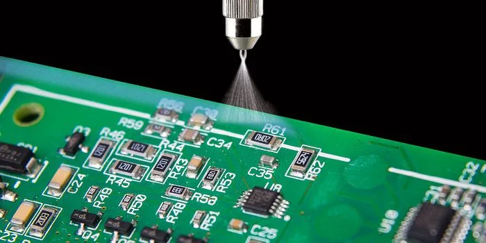
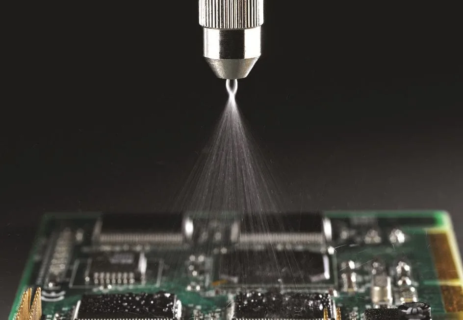
Conductive coatings convert plastic or composite enclosures into functional EMI shields. They are applied by spray, brush, or vapor deposition and work primarily through the reflection mechanism.
Key technologies:
- Silver-filled conductive paint: SE 60–80 dB at 30 MHz–3 GHz. Highest conductivity among coating options. Used in handheld electronics (smartphones, tablets), medical device housings. Higher cost due to silver content.
- Nickel-filled conductive paint: SE 50–70 dB. Lower cost than silver, good corrosion resistance. Most common for commercial electronics and industrial equipment.
- Copper-filled conductive paint: SE 60–80 dB. Good conductivity, requires protective topcoat to prevent oxidation.
- Vacuum metallization / sputtering: Thin-film deposition of aluminum or copper onto plastic. Extremely uniform coverage. SE 40–70 dB. High capital cost — used in high-volume consumer electronics (laptop lids, phone bodies).
- Plated polymer composites: Electroless plating of nickel/copper onto ABS or PC housings. Typical SE: 40–70 dB. Significantly reduces weight vs. metal enclosures — preferred in weight-critical aerospace and automotive applications.
Design note: Coated plastic enclosures may achieve SE = 40–70 dB on their panels, but seams and apertures must still be addressed with gaskets or conductive tape to avoid localized SE degradation.
EMI Shielding Material Selection Guide
Selecting the optimal EMI shielding material requires systematic evaluation across four criteria. The following decision framework is used in practice by EMC engineers to narrow material options before prototyping and compliance testing.
Step 1: Define the Frequency Range
Frequency is the single most important factor in material selection. The same material that provides 100 dB SE at 1 GHz may provide less than 10 dB SE against a 50 Hz power frequency magnetic field.
| Frequency Range | Primary Threat | Recommended Material Class |
|---|---|---|
| DC – 10 kHz | Low-freq magnetic (power lines, motors) | Mu-metal, silicon steel, high-μ alloys |
| 10 kHz – 1 MHz | Conducted EMI, power electronics | Steel, ferrite cores, thick copper |
| 1 MHz – 30 MHz | RF conducted/radiated | Copper, aluminum enclosures + conductive gaskets |
| 30 MHz – 1 GHz | Radiated RF (FCC Part 15, CISPR 25) | Aluminum/copper enclosures, conductive foam, metallized fabric |
| 1 GHz – 10 GHz | Wireless (5G sub-6, Wi-Fi 6, Bluetooth) | Conductive elastomers, EMI absorbers (3M AB6000HF), copper foil tapes |
| 10 GHz – 77 GHz | mmWave (5G FR2, automotive radar) | Specialized absorbers (>15 dB/cm at 10 GHz+), thin-film metal |
Step 2: Define the Required SE Level
Required SE is determined by the applicable regulatory standard and application criticality:
- Consumer electronics (FCC Part 15, CE EN 55032): 40–60 dB typically sufficient
- Industrial / automotive (CISPR 25, ISO 11452): 60–80 dB
- Medical devices (IEC 60601-1-2): 80–100 dB for life-critical systems
- Military (MIL-STD-461, MIL-STD-285): 100 dB minimum at 20 Hz–10 kHz; test to specific limits per system class
Step 3: Match Form Factor to Assembly Process
| Application Context | Recommended Form Factor | Example Products |
|---|---|---|
| PCB-level component isolation | Board-level shielding can (BLS), EMI absorber sheet | Metal BLS, 3M AB6000 series |
| Enclosure seam sealing | Conductive elastomer gasket, fabric-over-foam, BeCu fingerstock | LOCTITE SI 5421, Momentive SnapSil CXE16 |
| Cable shielding | Copper foil tape, conductive fabric tape, braid | 3M 9711S, VieTape EMI70 |
| Plastic housing EMI treatment | Conductive coating, vacuum metallization, plated polymer | Ni/Cu conductive paint, thin-film deposition |
| Flexible / conformal applications | EMI absorber sheet, conductive silicone pad | Gluditec EMI6425, BERGQUIST GAP PAD TGP EMI4000 |
| IP67/IP68 environmental + EMI | Form-in-place conductive silicone, conductive o-ring | Ni-graphite silicone FIP gaskets |
Step 4: Account for Environmental and Mechanical Constraints
- Temperature: Conductive silicone elastomers operate reliably from −55°C to +200°C. Conductive foam gaskets are typically limited to −40°C to +85°C. BeCu maintains spring properties up to +150°C.
- Galvanic corrosion: When dissimilar metals contact in the presence of moisture, galvanic corrosion accelerates. Aluminum housings should use nickel-graphite or silver-aluminum filled gaskets rather than copper-filled compounds to minimize corrosion risk. Always consult a galvanic compatibility chart during gasket material selection.
- Compression set: Gasket materials in repeated-open/close applications must have low compression set — BeCu fingerstock and conductive silicone elastomers outperform conductive foam in this regard.
- Outgassing: Aerospace and vacuum applications require low-outgassing materials per NASA ASTM E595. Silicone-based compounds require careful vetting — specify low-outgassing grades (TML <1.0%, CVCM <0.1%).
EMI Shielding Standards and Compliance
Product compliance requires selecting shielding materials that meet — and can be tested against — recognized standards. The most relevant standards for EMI shielding material selection and enclosure design are:
- IEEE Std 299 — Standard method for measuring SE of enclosures and rooms, 9 kHz to 18 GHz
- ASTM D4935 — Standard test for plane-wave SE of flat materials (30 MHz–1.5 GHz) — most commonly cited in material TDS
- MIL-STD-285 — Military standard for SE of enclosures; minimum 100 dB at 20 Hz–10 kHz
- MIL-STD-461 — Requirements for control of electromagnetic interference characteristics in subsystems and equipment
- IEC 61000-4 series — Immunity testing for industrial and commercial equipment
- CISPR 25 — Limits for radio disturbance characteristics in vehicles (automotive)
- IEC 60601-1-2 — EMC requirements for medical electrical equipment
- FCC Part 15 — US limits for unintentional radiators (commercial electronics)
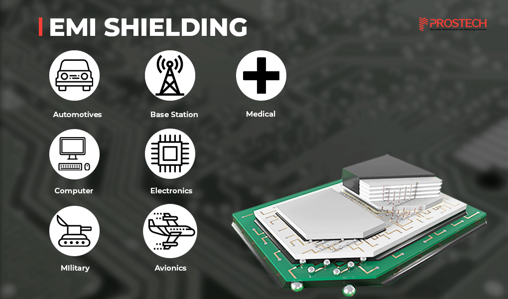
EMI Shielding Applications by Industry
5G and Telecom Infrastructure
5G base stations (gNodeBs) and small cells require multi-band EMI shielding across sub-6 GHz (LTE/NR) and mmWave (24–40 GHz) simultaneously. Conductive elastomer gaskets and EMI absorber sheets are used to control inter-module interference within the radio unit, while aluminum or zinc die-cast housings provide system-level shielding. Critical challenge: maintaining SE while providing thermal dissipation paths for high-power PAs.
Automotive and EV/xEV
Modern vehicles contain 80–100+ ECUs generating and receiving signals across a wide frequency span. CISPR 25 Class 5 limits require SE up to 1 GHz for vehicle electronics. EV battery management systems (BMS) face particular challenges: the high-voltage power conversion circuits (switched at 10–100 kHz) generate conducted and radiated EMI that can disrupt CAN/LIN communication buses, GPS receivers, and ADAS radar modules (77 GHz). Conductive silicone gaskets with combined EMI/thermal function (e.g., Momentive SnapSil series) are widely adopted in xEV electronics packaging.
Medical Devices
IEC 60601-1-2 mandates that life-critical devices function in environments with field strengths up to 10 V/m (3 V/m for implantables), requiring SE of 60–100 dB. Implantable devices (pacemakers, neurostimulators) use hermetic titanium or stainless steel housings. Diagnostic equipment (MRI, CT, ultrasound) requires both shielding of internal electronics and shielding of the device from external fields. Low-outgassing materials and biocompatibility are non-negotiable constraints in material selection.
Aerospace and Defense
MIL-STD-461 and MIL-STD-285 set the performance floor for all military electronics. Nickel-graphite and silver-aluminum filled silicone gaskets are used for their combination of high SE (70–110 dB), broad temperature range, and corrosion resistance. Minimizing weight is as critical as meeting SE targets — plated polymer composites, carbon-fiber laminates with conductive coatings, and thin-film aluminum deposition are enabling technologies.
Industrial and IoT
Factory automation environments expose electronics to high-power motor drives, welding equipment, and variable-frequency drives (VFDs) — all strong EMI sources across 1 kHz–100 MHz. Industrial control systems and safety PLCs require SE of 60–80 dB minimum. IoT sensor nodes face the additional challenge of integrating antennas (2.4/5 GHz Wi-Fi, sub-GHz LoRa) in close proximity to power electronics — requiring careful selection of absorber materials to isolate antenna performance from conducted EMI.
Electronic Devices and Components That Require EMI Shielding
The following component and system categories are most commonly protected with EMI shielding in modern electronics design:
| Device/Component | Primary EMI Risk | Typical Shielding Approach |
|---|---|---|
| System-on-Chip (SoC), Application Processors | Radiated emissions from high-speed clocks and buses | Board-level shielding can (BLS), EMI absorber over package |
| RF/Wireless Modules (Wi-Fi, Bluetooth, 5G) | Self-interference, co-existence with other radios | Module-level BLS, EMI absorber sheets for isolation |
| Power Amplifiers | Broadband harmonic radiation | Aluminum/copper shield can, conductive gaskets |
| DC-DC Converters / SMPS | Conducted EMI on power rails (100 kHz–30 MHz) | Ferrite chokes + shielded inductor, conductive housing |
| FPGA / High-Speed Digital | Clock harmonics, DDR memory bus radiation | Spread-spectrum clocking + BLS, EMI absorber pads |
| Automotive Radar (77 GHz) | mmWave spurious emissions, cross-sensor interference | Absorber panels, precision metal shielding, PCB-level isolation |
| Implantable Medical Devices | External field susceptibility (MRI, defibrillator) | Hermetic titanium/stainless housing, filtered feedthroughs |
| Camera Modules (ADAS, smartphones) | EMI from nearby digital circuits corrupting image sensor | EMI absorber sheets, conformal EMI coating on FPC |
Frequently Asked Questions
What is EMI shielding?
EMI shielding (Electromagnetic Interference Shielding) is the practice of surrounding electronic components, circuits, or cables with conductive or magnetic barrier materials to block, reflect, or absorb electromagnetic interference (EMI) and Radio Frequency Interference (RFI). The goal is to prevent external EM fields from disrupting sensitive electronics and to prevent emissions from leaking into the surrounding environment.
How does EMI shielding work?
EMI shielding works through three primary mechanisms: (1) Reflection — conductive materials reflect EM waves at the surface due to impedance mismatch; (2) Absorption — EM energy is converted to heat as it propagates through the material; (3) Multiple Reflection — in composite or thin shields, waves bounce between internal surfaces for additional attenuation. The total shielding effectiveness (SE) is expressed in decibels (dB) and equals the sum of all three contributions.
What are the most effective EMI shielding materials?
The most effective materials by shielding effectiveness: copper (SE >100 dB at GHz frequencies, σ = 5.8×10⁷ S/m) leads for broadband high-frequency performance; mu-metal (μr >20,000) leads for low-frequency magnetic shielding; conductive silicone elastomers (SE 70–110 dB, 10 MHz–10 GHz) lead for flexible gasket applications; EMI absorbers like 3M AB6000HF (200 MHz–18 GHz) lead for board-level near-field noise suppression where reflected energy is undesirable.
What is EMI shielding effectiveness (SE)?
Shielding Effectiveness (SE) is the attenuation of an EM field provided by the shielding material, measured in decibels (dB). SE = 20 dB means 90% attenuation; 40 dB = 99.99%; 60 dB = 99.9999%; 100 dB = essentially complete. SE is frequency-dependent and must be verified over the target frequency range using IEEE Std 299 or ASTM D4935 test methods.
What are the 3 mechanisms of EMI shielding?
The three mechanisms are: (1) Reflection Loss — EM waves reflected at the material surface due to impedance mismatch with free space; (2) Absorption Loss — EM energy dissipated as heat within the material, proportional to conductivity × permeability × frequency × thickness; (3) Multiple Reflection — additional attenuation from internal surface reflections within thin or composite shields.
How do I choose the right EMI shielding material?
Select based on four criteria: (1) frequency range — mu-metal for DC–100 kHz; copper/aluminum for 30 MHz–10 GHz; absorbers for 200 MHz–18 GHz; (2) required SE level — 40–60 dB for commercial, 60–80 dB for automotive/industrial, 80–120 dB for military/medical; (3) form factor — BLS can for PCB level, elastomer gasket for enclosure sealing, conductive tape for cable; (4) environment — temperature, corrosion, galvanic compatibility, compression cycle life.
What EMI shielding standards must products comply with?
Key standards: FCC Part 15 (USA), CE/ETSI EN 55032 (Europe), CISPR 25 (automotive), IEC 61000-4 (industrial immunity), IEC 60601-1-2 (medical), MIL-STD-461 and MIL-STD-285 (military). SE is measured per IEEE Std 299 (enclosures) or ASTM D4935 (flat materials).
What is the difference between EMI shielding and EMI absorption?
Reflective EMI shielding (copper, aluminum, steel) reflects EM waves away — highly effective across broad frequencies but may cause interference by redirecting energy. EMI absorption (ferrite composites, 3M AB6000 series) converts EM energy to heat — preferred for board-level near-field applications where reflected energy would couple back into adjacent circuits. Modern solutions like 3M AB6000HF combine both: a metallic shielding layer for broadband SE plus a magnetic absorbing layer for targeted 1–3 GHz performance.
EMI Shielding Solutions from PROSTECH
PROSTECH is an authorized distributor of EMI shielding materials from leading international manufacturers including 3M, Henkel/LOCTITE, Momentive, tesa, Gluditec, and t-Global. Our EMI shielding portfolio covers all material categories described in this guide — from EMI absorber sheets and conductive silicone gaskets to shielding tapes and conductive coatings — with full technical support for material qualification and application development.
For engineers and procurement professionals in Vietnam and Southeast Asia, PROSTECH provides:
- Technical material selection assistance based on your frequency requirements and compliance targets
- Sample materials for prototype testing and qualification
- Application engineering support for complex multi-material EMI challenges
- Local inventory and supply chain support for production-volume requirements
Contact our EMC/EMI technical team for material selection support:
Browse EMI Shielding Products | Request Technical Consultation

<!– ================================================================ END JSON-LD SCHEMA BLOCKS