Why is Thermal Management so crucial in Electronic packaging?

.

.
Up to 55% of failures on electronic circuit boards are caused by heat
The result in temperature increasing will affect the operation of the active and passive devices in the integrated circuits. If the temperature increase is high enough, the active or passive devices being heated may either not work properly or even totally fail. Such failures include thermal runaway, junction failure, metallization failure, corrosion, resistor drift, and electromigration diffusion. Therefore, it is crucial to minimize any temperature increase in an electronic package.
What causes temperature increase in an electronic package?
- Increasing power density and current levels
The insatiable demand for higher performance processors has led to a steady escalation in power consumption across all the market segments, such as mobile and performance desktops as well as servers and workstations. Increasing power density and current levels in the microprocessors have been main heat sources and cause concerns to do the thermal management of the on-chip hotspots as well as the package and interconnection Joule heating.
- Higher density of components in PCBs surface
Another cause for concern about thermal management on an electronic circuit board is, The electronic industry field is witnessing the increasing trend of thinner and smaller handheld devices and household appliances. That is why the PCB is more compact, the spaces among components on electronics PCBs are getting closer and closer, making the heat harder to transfer out of PCBs components.
How to manage the produced heat on the PCB?
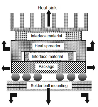
The objective of thermal management in electronic packaging is to efficiently remove heat from the package to the ambient environment. The main Cooling methods in the Thermal Management function around basic heat transfer modes – i.e., conduction, convection, and radiation – and the development of technologies is moving from single-phase heat transfer to multi-phase heat transfer. The cooling technologies such as thermal vapor chamber, cold plates and jet impingement mechanisms have revolutionized the future of the thermal management landscape.
To cool an electronic circuit board, a combination of heat transfer methods is often used to optimize heat dissipation efficiency. The most common is thermal conduction combined with thermal convection.
- Conduction cooling: heat transfer from hotter part to cooler part by direct contact.
- Convection cooling: heat transfer between two surfaces as a consequence of a relative velocity between them.
Thermal interface materials-TIMs
Talking about the phenomenon of heat conduction between two direct contact surfaces:
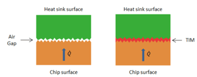

Any engineering surface of the electronic components is rough on a microscopic level due to the presence of microscopic asperities. When two such rough surfaces come into contact during assembly of electronic packaging, the actual contact occurs only at a few discrete spots, usually at the high points of the two mating surfaces. Typically, the ratio of real contact area to apparent contact area is approximately 1–2%. The surounding gap is fill with air with very low thermal conductivity (~0.026 W/m.K), which greatly reduces the overall heat transfer efficiency.
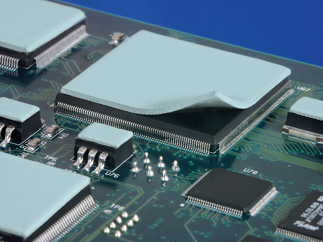
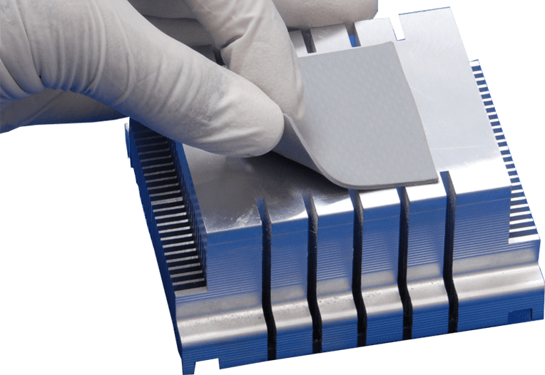
Thermal Interface Materials (TIMs) are the metarial that are inserted between two surfaces to replace air gaps i.e, in order to enhance thermal coupling between them.
Although TIMs typically have lower thermal conductivity than the substrate (normally varies from 1-7 W/m.K, even much higher in special cases), it is still many times higher than that of air ( 38-270 times). At the same time, they are highly compliant to conform to the geometry of the adjacent rough surfaces.
Discover General Types of Thermal Interface Materials-TIMs
How to choose the suitable TIMs?
The right TIMs are determined by your package design so that specific materials with desired properties can be selected to meet your requirements. Below are some factors to consider when choosing the right thermal interface materials TIMs.
- Temperature range of your PCB/ electronics device: Silicone TIMS, e.g. gap fillers are rated to higher temperatures than silicone free interface materials.
- The gap space between the heat source and the heat spreader? As a rule, the thinner the TIM the better, but because mating surfaces are never perfectly flat, a minimum material thickness may be needed to accommodate non-flatness issues.
- Thermal conductivity, in W/mK, measures a material’s ability to conduct heat regardless of its thickness. A bulk measurement, thermal conductivity values can be used for comparing TIMs, but it does not describe a TIM’s ability to minimize contact resistance in an application.
- Thermal impedance is the important specification measured in degrees Kin2/W. It is an application-specific measure of the ratio of the temperature difference between two mating surfaces to the steady state heat flow through them. Thermal impedance usually decreases with added mounting pressure and contact area, but increases with the thickness of the TIM.
- Surface flatness of mating surfaces is important for determining the type of material. If both surfaces are flat, grease or thin films would be ideal choices, but that is seldom the case. Plastic IC’s are typically concave in the center and if the heat sink is extremely flat, the contact area would be limited to the periphery leaving an air pocket in the center.
.
- Electrical isolation, measured in kV, is sometimes needed. Silicone-based TIMs provide this property, along with thicker materials such as gap fillers. Thinner phase change materials and greases may not be reliable electrical insulators. Graphite is electrically conductive.
- Compressibility is important when working with irregular surface as when covering a number of components. If heat and excess pressure are applied to a silicone-based TIM, silicone can escape and migrate along the PCB. Without sufficient pressure there may be excess thermal resistance across the interface.
- UL flame class rating. A UL flammability rating requirement is needed for many TIM applications. Most of these materials are available with V-0 ratings, which will meet most needs.
- Silicone or silicone free. Silicone is an excellent thermal material with a high temperature range but some applications, e.g. in space, can’t use it due to outgassing.
- Ease of application. The method of attachment is a cost and performance decision. Most small heat sinks are attached with a double sided thermal adhesive tape. Larger heat sinks require mounting hardware. Adhesives can be added to both or one side of the thermal material. However, with a layer of adhesive, thermal impedance will be increased.
- How easy are the materials to work with in a manufacturing environment? How easy are they to re-work when heat sinks must be removed? Some gap fillers can be re-used, but phase change materials and grease must be replaced
.
In addition to material properties, designers should consider automated assembly processes and the ease with which certain solutions can be integrated into a PCBA or enclosure during manufacturing. The thermal interface materials come in both solid and liquid forms. It gives designers some flexibility to choose the material that will work best for their components, application, and assembly process.
Contact to discuss more with our experts through:


